|
 Optical
inspection systems Optical
inspection systems
|
|
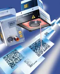
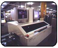
Automated
Optical Inspection (AOI) systems have reached a
price/performance point at which they can be used
in-line to detect several important assembly defects.
Systems using visible light are among the fastest
and least expensive. They can replace human inspection
of circuit assemblies, and provide data to improve
control over assembly processes.
Automatic
Optical technique been in use in PCB manufacturing
have existed for almost two decades, and these techniques
hold out the promise of a non-contact detection
alternative for some classes of process defects.
Historically, however, such automatic systems have
been plagued with long inspection times, high fault
escape rates and higher false flag rates, factors
that precluded broad deployment into modern high-speed
production lines and lights out factories.
|
|
|
New
generation AOI systems having sophisticated vision
algorithms, multiple, broad optical data pathways
and accurate mechanical and optical systems are
just now emerging, and are finally able to deliver
on the simultaneous promises of high speed and high
reliability detection.
|
|
Vision
System Alternatives
|
|
Just
as with electronic test equipment, there are several
classes of vision inspection equipment.
- The
machine-vision industry has a wide range
of equipment vendors and systems integrators
for rack and stack vision systems. Software
tool-kits provide an extensive suite of
image-processing algorithms and graphical
tools to simplify the programming of inspection
tasks. They are suitable for low-cost, very
specific inspections of a device or assembly.
But users must be well-versed in vision
systems design to build an effective inspection
system. Just like rack-and-stack test systems,
these inspection systems tend to be customized
for an individual application and require
considerable re-programming for each new
board design.
- General-purpose
PCB inspection and gauging systems are fully-integrated
systems containing XY stage, cameras, flexible
lighting and board transport. They are capable
of operating in-line to measure and inspect
components on circuit boards, using a variety
of inspection techniques. These types of
systems offer precise measurements, flexibility
and speed.
- Specialized
PCB inspection systems, designed to be operated
in-line immediately after a solder paste
or part placement operation, that are optimized
for detecting assembly defects from that
operation at the highest throughput possible.
These types of systems offers low cost and
fast, simple, CAD-driven programming for
new circuit board designs. However their
measurement capabilities may not be as precise
or as flexible as general-purpose machines.
These systems are the Manufacturing Defect
Analyzers (MDAs) of the vision inspection
world.
|
|
|
|
Defect
Coverage
|
|
Vision
systems used after a placement process, are capable
of detecting the following defects:
- Missing
part.
- Non-resident
part present by mistake.
- Mis-oriented
(backwards) part.
- Part
offset and rotation measurement.
- Location
of odd-form components and hardware.
|
|
|
When
used after a solder process, vision systems can
detect solder bridges. However, attention is shifting
to vision inspection of solder paste immediately
after the paste is printed, since many solder defects
can be attributed directly to printing defects and
are more easily detected at this stage.
|
|
|
|
Economics
|
|
For
a vision inspection system to be economically justifiable
in a high-volume PCB assembly operation, it must:
- Operate
in-line at line beat rates (30 seconds or
less).
- Offer
a high degree of defect coverage for the
targeted defects (90% or more).
- Provide
measurement data to data-collection systems.
- Have
low initial purchase cost.
|
|
- Offer
fast, simple programming for new board designs
(a few hours to generate an initial inspection
plan), and allow fast re-programming for
design changes. Ideally the programmer should
not require any specialized vision knowledge.
- Be
tolerant of normal manufacturing variations
(for example, component color and marking
changes caused by components from different
vendors). It should not be necessary for
the programmer to tweak the inspection
plan to cope with such changes.
- Have
very low false-accept and false-fail rates.
False-accepts
can lead to potentially bad product being shipped.
Failures are diverted to a repair loop, so a high
proportion of false failures wastes resources and
brings the systems trustworthiness into doubt.
Some parts just cannot be inspected reliably. Ideally
the system should detect this to prevent false calls
on such parts.
|
|
What
makes a good AOI system?
|
|
What
are the key inspection challenges that must be overcome
by modern AOI systems to make them competent, consistent,
and reliable? They fall into three main areas of
technology, the lighting system, the imaging system,
and the motion system. Any solution must excel in
all three areas to produce a system that is reliable,
repeatable, and can properly detect defects without
false calls and/or escaped defects.
|
|
|
|
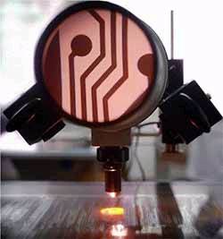
The
Lighting system
|
|
|
|
Lighting
is extremely important. One example: when inspecting
a solder joint, it is not sufficient to merely light
up the scene in a generic way. The lighting must
be flexible and configurable enough to bring out,
or highlight one or more characteristics of the
solder joint, and these must be characteristics
that uniquely indicate that the joint has the proper
shape and volume. That same lighting configuration
must also definitively produce enough variation
on a bad joint to obtain reliable differentiation.
To isolate the proper characteristics and also differentiate
good from bad, a highly structured, precise and
programmable lighting tool is required. This tool
must be able to properly illuminate the target from
all directions, relative to the board and relative
to any of cameras. It must also be able to provide
precise directional control and intensity to deal
with shadowing and obstructions created by nearby
components.
A
best approach is an array of high precision point-source
light emitters such as LEDs. The LED array provides
a large number of precision lighting angles, and
permits fine control of the intensity and direction
of the light. Additional benefits of LED technology
are consistency and reliability. The intensity of
a LED emitter however is constant over the life
of the equipment. LED arrays require no service
at all for the life of the equipment.
|
|
|
|
The
Imaging system
|
|
The
second core competency in a high-performance AOI
system is the imaging system, sometimes referred
to as the vision system. There are two classes of
imaging systems: vertical camera only systems, (called
2D or two-dimensional), and 3D or three-dimensional
systems. The 3D systems incorporate angled cameras.
2D systems are of course cheaper to build, and simpler
to use, but they have some inherent limitations
in fault coverage. Imagine that your own eye is
looking down a tube while you are inspecting a board.
Certain
defects such as lifted gull-wing leads are very
difficult to see with a single, straight-PCB down
satellite view of the board. Angled cameras are
much more advantageous for detecting this very important
fault category. Some 2D systems attempt to overcome
their lack of angled cameras by using color. One
approach is to use a vertical camera with colored
lights at various angles; these lights produce a
color banding profile on the top of a gull-wing
lead.
|
|
|
|
|
From
that banding profile one can indirectly infer that
perhaps the lead is lifted and not making contact.
Angled cameras provide a more direct, positive sensing
capability in that by nature, they can see the
position of the lifted lead directly, and without
inference.
Four
angled cameras are typically employed in a 3D system
one each to cover north, south, east, and west
in addition to a single vertical camera. When
using angled cameras at high magnification, board
wrap page becomes a very significant issue. A small
amount of warp can move the target image completely
out of the inspection window. Therefore, a modern
AOI system must have a competent warp correction
system. Some systems make only a single height correction
for the entire board, but warp correction should
be more comprehensive, compensating at every field
of view (FOV). Comprehensive warp correction ensures
accurate placement of the inspection window and
eliminates yet another source of false calls.
A
common question is whether color or monochrome imaging
is best. When considering all types of imaging systems,
the answer is both. In certain applications such
as metrology, color is valuable, but for the mainstream
post-reflow use, which is the area of concern for
this discussion, color is not a requirement, and
actually can be a hindrance. As mentioned earlier,
it is important that the lighting configuration
be able to highlight the solder joint characteristic
that uniquely indicates that the joint has the proper
shape and volume. In other words, it is desirable
to bring out the indicative qualities of the image
so that we attain the highest possible signal-to-noise
ratio. The same concept is true for the imaging
components. By using monochrome lighting and cameras,
the resulting image data is spectrally pure, and
it is relatively easy to analyze the data and differentiate
out the salient components of the image. Color systems
generate much more data and yield more spectral
clutter that obscures the salient characteristics.
The
optics employed in the front end of a vision system
must be able to deliver meaningful images to the
rest of the imaging system. Generally speaking,
to inspect todays printed circuit assemblies including
0201 packages a minimum pixel resolution of 20 to
30 microns is required to have enough pixels in
the image to reasonably map the target. A high-resolution
image generates abundant data. In fact, in a single
inspection pass, hundreds of Megabytes of image
data can be generated. A high bandwidth image capture
system is required to maintain a high basic scan
rate. To maintain throughput, these systems must
have an extremely high-bandwidth data pathway, which
processes image data in parallel. The required level
of performance cannot be achieved by using off-the-shelf
components; the cameras, synchronization system,
frame grabbers and memory transfer mechanisms must
be optimized for processing rates on the order of
hundreds of frames per second. The resulting images
must be either analysed on the fly, or stored for
later analysis out of the critical timing path.
|
|
|
|
The
Motion system
|
 |
|
The
third crucial element of a world-class AOI system
is the mechanics, or motion system. The requirement
here is to move the camera relative to the board
quickly, yet be able to capture very stable images
on the fly. Very few systems attempt move-and-stop
type operation - it is far too problematic from
a physics standpoint, and greatly reduces throughput.
Similarly, moving the board rather than the camera
is a concept fraught with trouble as the board being
inspected is an uncontrolled variable to the AOI
motion system, and can cause unwanted vibration
amongst other undesirable effects.
To
capture stable images on the fly, the camera head
must be completely rigid on its mount, and must
be driven through its center of gravity to eliminate
any vibration. Similarly, the XY camera positioning
system that moves the head must be cleanly designed
and solid to minimize positional tolerances. The
XY camera positioning system must be powerful and
precise and have active feedback, which can read
actual position data to the micron resolution level.
The high-resolution encoders are also the key to
synchronizing the camera exposures
the firing
of the cameras on the fly at high speed as they
traverse the board. All of these characteristics
of a high-performance motion system are necessary
to ensure that the cameras are positioned correctly
to deliver the correct images to the software system
so that the image analysis algorithms can operate
on the intended data.
|
|
|
|
Bringing
it all together
|
|
How
do these the lighting, imaging and motion systems
work together during board inspection? After the
board has been conveyed into place, the motion system
and imaging systems activate to locate the fiducials
marks so that all inspection windows can be registered
properly to the board. A warp scan occurs either
prior to or integrated with the actual optical inspection
pass, correcting some angled camera window positions
as required by the curvature of the current board
being inspected. Warp must be sampled and corrected
for uniquely at every field of view across the board.
As
the inspection scan progresses, the motion system
smoothly drives the camera head across the board
and images are captured on the fly during this continuous,
non-stop motion. The lighting and imaging systems
are synchronized to the motion system through the
use of high precision encoders that report the actual
position of the camera head in real time. Accurate
positional feedback is critical to ensure that the
correct lighting mode fires at the right time, and
that the electronic camera shutter captures the
image at that same moment. Once a particular field
of view (FOV) image has been captured by the frame
grabber, it is block transferred at high speed into
memory so that image analysis can begin as scanning
continues. Image analysis is the quintessential
activity that is the inspecting of the devices
on the board. Many types of inspections are done
on each component, and each inspection is typically
performed by individual inspection windows that
were laid out over the image of the device by the
generic AOI device model when the inspection program
was originally created.
All
of the above performance requirements in the areas
of lighting, Imaging, and motion control systems
(Lights, Cameras and Action) are crucial in creating
a viable high performance AOI system. All three
categories are mandatory and must work together
to make the overall technology competent just as
a tripod must have all three legs to stand.
We
offer a broad line of products for building your
own sophisticated visual inspection system. Our
programmers will write specialized tailor software
to make your inspection process best suitable for
your requirements. We provide flexible integration
of our systems into your technological process.
If you look for powerful and cheap inspection system,
dont hesitate to contact us!
|
|
|
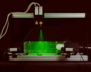
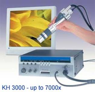
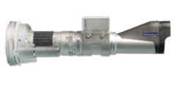
3-D
video-microscope inspection system for a variety of applications
|
|
|
|
Use
the breakthrough in superior microscopic technology:
- 7000x
the highest inspection power
- 3D
rotary head adapter (360 degree rotation)
- Measurement
tool (point to point, circumference, radius,
angle, area, counting,...)
- video
for PC (resolution up to 2.1 Megapixels
at 30 frames per sec.)
|
|
|
|
|
 go to product
order go to product
order
For any particular request please
contact:
info@flokal.eu
|